Functions / Settings
General Informations
Very important ! Do not bend any of the spring contacts.
Do not turn the rotor on the long brown shaft, otherwise the contacts on the rotating body will not function properly (see yellow indicator in Fig 1 below).
Setting Idle Signal
The red indicator shows the exact idle position of the rotating body.
Between pin 12 and pin 17 the measured value 0 to 1.0 Ohm must be displayed on the Ohm Meter.
Hold the rotor in the clockwise final position as shown in Fig. 4 below, using only your thumb and index finger. The contact on the post at the green arrow must be closed.
When installed in the car, the rotor is hold back by the return spring on the throttle shaft, provided the basic setting of the throttle and TPS is correct.
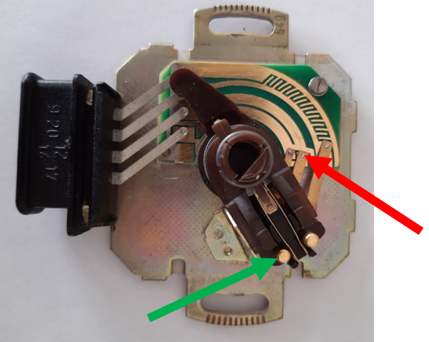
Fig.1: Rebuilt TPS with new printed circuit board (PCB)
By turning the gaspedale back clockwise, the contact at the green indicator will be closed. This is the position for the „Thrust Cutoff“.
The end position is at the idle stop position. Contacts between pin 12 and pin 17 are closed. The measured value indicate 0 to 1.0 Ohm (completely clockwise)
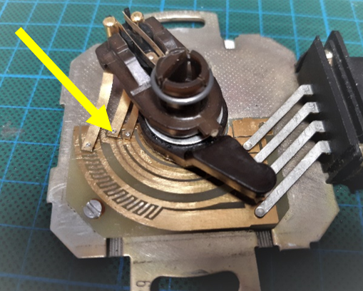
Fig.2: Idle position of the TPS rotating body
The second sliding contact (yellow indicator on above Fig. 2) must be positioned on the lowest small board contact pad.
If this position cannot be achieved by turning the rotating body, the stop tab, as shown in Fig. 3, must be readjusted carefully by turning it counterclockwise until it matches the setting as shown in Fig. 2.
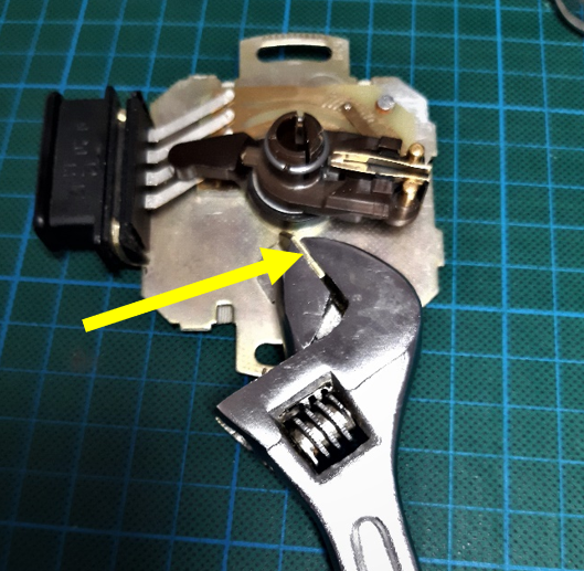
Fig.3: Re-adjustment of the idle stop tab
When the idle signal between pin 12 and 17 is adjusted correctly, the measured value shown should be between 0 and 1.0 Ohm).
Settings of additional acceleration pulses
Connect pin 12 and pin 20 to an Ohm Meter and turn the rotor part very slowly counterclockwise.
Do so by holding the rotor as shown in Fig. 4 below, using your thumb and your index finger.
The two contacts on the rotor body move easily when the rotorbody is beeing moved slightly to either side.
Do not move the contacts by turning the brown handle, the contacts will not adjust correctly.

Fig.4: (Move as when installed on the throttle shaft)
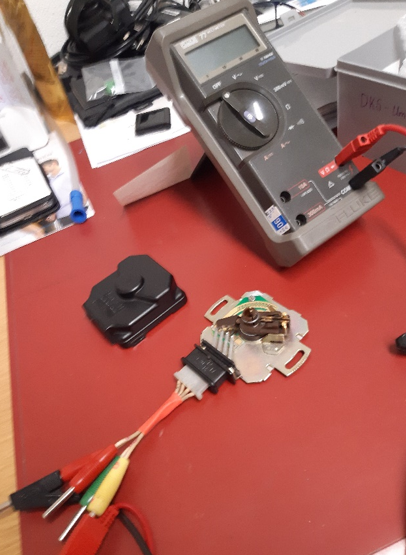
Fig.5: TPS testing with Ohm Meter and self made test adapter
Triggering the additional acceleration pulses
Close the contact at the yellow indicator by turning it counterclockwise and trigger the additional injection pulses via the sliding contact at the red indicator.

Fig.6
Red indicator: Contact slides over the PCB ridge for the additional injection pulses when turned
Yellow indicator: Contact for additional injection pulses (connection of pin 12 with PCB ridge via contact post).
Now the pulses of the inner PCB ridge between pin 12 and pin 20 and, on the outer PCB ridge between pin 12 and pin 9 should be displayed on the Ohm Meter when opening and closing.
When turning back, no more pulses should be visible (Thrust Cut-off). See following chapter.
Thrust Cut-Off Function
When turning clockwise, the contact at the yellow indicator must be open in order not to trigger any additional pulses. The thrust cut-off is active.
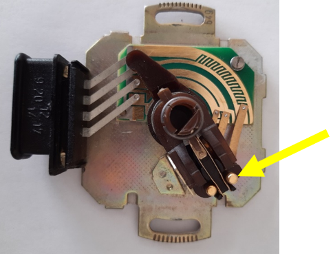
Fig.7
Pendulum Contacts
These two contacts are responsible for the acceleration pulses (red) and the thrust cut-off (yellow) when the accelerator pedal is released.
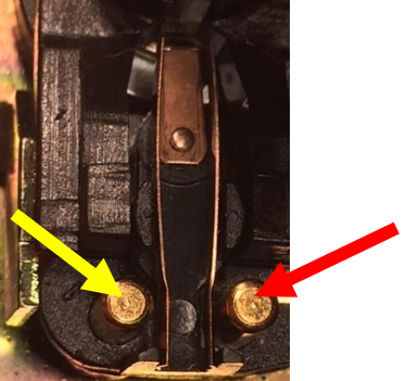
Fig.8
If the measurement of the idle signal shows too high ohm values, slight traces of oxidation on the brass posts and the contact springs may be the cause. They can be polished off carefully with the help of a polishing cloth / sandpaper (1200 grain). This will reduce the contact resistance. If this is below a value of approx. 1 Ohm, it is sufficient.
Very important: Do not bend any of the spring contacts !
Should the pulses still do not work properly, the graphite head on the slip ring may have been damaged. This can be caused by improper handling (sanding or filing) or too much wear due to aging.
(Contact heads can also be made of brass or bronze for newer TPS).
If this is the case, the graphit head makes a constant short circuit between the two ridge contacts pin 9 and pin 20 when sliding over the ridge. When turning counterclockwise no additional injection pulses for the optimum acceleration values can be measured at pin 20 or pin 9 anymore and a short circuit is indicated at the Ohm Meter.
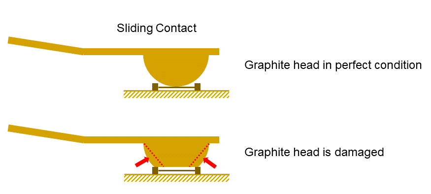
In the case of damaged contact heads, it may be possible to achieve an improvement by very careful machining of the zones marked in red. This should be done with a very small and fine file, so that the short circuits over the conductive paths with the excessively wide contact heads are prevented. When doing this, always work at right angel to the conductive path ridges. This rework on the contact heads should be done under a microscope or other suitable visual aid and by holding the contact with suitable tweezers. The file should also not be used to touch the traces or bend the contact springs. (Protect them with thin plastic foil).
Important notice: During this mechanical intervention on the contact heads, too much material removed can destroy the contact head, which makes the TPS unusable. Therefore, under repeated measurements between pin 9 and 20 with the ohmmeter, minimal removal of the head material can be ensured.
The author of this document gives no guarantee that the rework can be successful. It is only a last attempt to protect the TPS from final disposal.
